Overview of the Elite Gourmet Bread Maker Recipe Book PDF
The Elite Gourmet Bread Maker Recipe Book PDF offers curated recipes for advanced home bakers, featuring step‑by‑step guidance, ingredient sourcing tips, and machine‑specific settings. It blends classic techniques with modern twists, ensuring consistent results across models.Ideal for all levels now.
Purpose and Target Audience
Designed for culinary enthusiasts who own a bread‑making appliance, the Elite Gourmet Bread Maker Recipe Book PDF bridges the gap between novice experimentation and professional‑grade loaf production. Its primary purpose is to provide a comprehensive, machine‑centric reference that streamlines the baking process through calibrated timing charts, ingredient‑specific ratios, and troubleshooting guidelines tailored to the most popular models on the market. The book’s target audience includes home bakers who are eager to elevate their bread‑making skills, culinary students seeking a practical supplement to textbook theory, and hobbyists who appreciate the convenience of a programmable appliance. By offering a curated selection of classic sourdoughs, artisanal baguettes, and specialty sweet breads, the PDF invites readers to explore flavor profiles that would otherwise require extensive trial and error. Additionally, the guide serves as an educational tool for those interested in the science of fermentation, dough development, and crust formation, providing clear explanations of how temperature, humidity, and kneading cycles interact within a bread maker’s controlled environment. Whether the reader is looking to replicate bakery‑quality results at home or simply wants to experiment with new recipes, the Elite Gourmet Bread Maker Recipe Book PDF delivers a structured, accessible resource that empowers users to achieve consistent, high‑quality loaves with minimal effort. This guide equips bakers with precision and for every loaves!
Historical Evolution of Gourmet Bread Recipes
From ancient grain milling to modern artisanal techniques, gourmet bread has evolved through exchanges and fermentation. Bread makers capture this legacy, enabling control over dough, proofing, crust formation for consistent,!highquality results.
From Traditional to Contemporary Techniques
The evolution from hand‑milled loaves to programmable bread makers marks a pivotal shift in gourmet baking. Traditional techniques relied on manual kneading, natural fermentation, and open‑fire baking, demanding years of apprenticeship. Contemporary methods harness precise temperature control, automated mixing, and advanced proofing cycles, allowing even novices to replicate artisanal textures. The Elite Gourmet Bread Maker Recipe Book PDF bridges this gap by offering step‑by‑step instructions that honor time‑honored rituals while integrating modern technology. It details how to adjust hydration for sourdough starters, employ autolyse for gluten development, and use stretch‑and‑fold protocols to build structure without manual labor. By providing machine‑specific settings—such as dough‑mixing speed, kneading duration, and baking temperature—readers can consistently achieve crusty exteriors and airy interiors that once required a seasoned baker’s touch. This hybrid approach preserves the flavor depth of slow fermentation while delivering the convenience of automation, redefining what it means to craft gourmet bread at home.
By leveraging the PDF’s detailed machine‑specific settings, bakers can experiment with hydration ratios, fermentation times, and crust‑crisp profiles, turning each loaf into a laboratory of flavor that satisfies both traditionalists and tech‑savvy enthusiasts alike, ensuring every bake is a triumph of science and art. The PDF also includes a troubleshooting guide that quickly resolves common dough issues!
Essential Bread Maker Models Recommended
The Elite Gourmet PDF recommends three top models: the KitchenAid KBD-200 for its robust motor, the Breville BMB820XL for precise temperature control, and the Cuisinart CBK-200 for its versatile settings. Each offers programmable cycles, dough‑mixing, and baking modes ideal for gourmet loaves. today now soon
Top Features for Gourmet Baking
Top models feature precise temperature control, allowing bakers to set the exact heat profile for each loaf. Programmable cycles let users choose from classic, artisan, or quick‑bake modes, while auto‑dough settings mix, knead, and rest without manual intervention. Advanced sensors monitor humidity and dough consistency, adjusting water addition on the fly to keep the crumb structure ideal. Smart connectivity via Wi‑Fi or Bluetooth lets users start, pause, or monitor progress from a smartphone app, and firmware updates add new recipes and performance tweaks. Dual‑motor systems provide stronger kneading power, reducing over‑mixing and improving gluten development. Built‑in delay‑start timers accommodate busy schedules, and a dedicated crust‑control dial offers options from light to dark, even a “glaze” setting for a glossy finish. Finally, a transparent dough‑dispenser window lets bakers observe the mixing process, ensuring no lumps or dry patches remain. These features combine to deliver restaurant‑quality breads at home.
For enthusiasts, the PDF also includes a troubleshooting guide that explains how to adjust hydration percentages for different flour types, how to use a digital scale for precision, and how to calibrate the machine’s temperature sensor. It offers a glossary of baking terms, a conversion chart for metric to imperial measurements, and a section on seasonal ingredient substitutions that keep breads flavorful year‑round. Readers can also find a QR code linking to video demos. QR demo
Core Ingredients and Their Quality Standards
The Elite Gourmet Bread Maker Recipe Book PDF prioritizes premium ingredients: 100% organic wheat flour, natural sourdough starters, and certified yeast. It specifies moisture, protein levels, and filtered water for consistent rise. For depth and aroma
Flour, Yeast, and Specialty Additives
In the Elite Gourmet Bread Maker Recipe Book PDF, ingredient selection is treated as art. The guide recommends flours ranging from high‑protein bread flour (11–12% protein) to low‑protein pastry flour (7–8%) and blends like whole‑grain rye and spelt. Each flour type pairs with a specific hydration level and mixing time to unlock maximum flavor and crumb. The book stresses flour freshness, advising bakers to store it in airtight containers and use it within 90 days to preserve enzymatic activity!!
Yeast selection is pivotal for texture and flavor. The PDF contrasts active dry yeast, which requires proofing, with instant yeast that can be added directly. It details optimal temperatures (75–80°F) and hydration ratios for each type. For sourdough lovers, the guide explains how to maintain a healthy starter, feeding schedules, and the impact of temperature on fermentation speed. Nutritional yeast is highlighted as a savory enhancer, adding umami without leavening. It also covers yeast storage guidelines.!!!!!
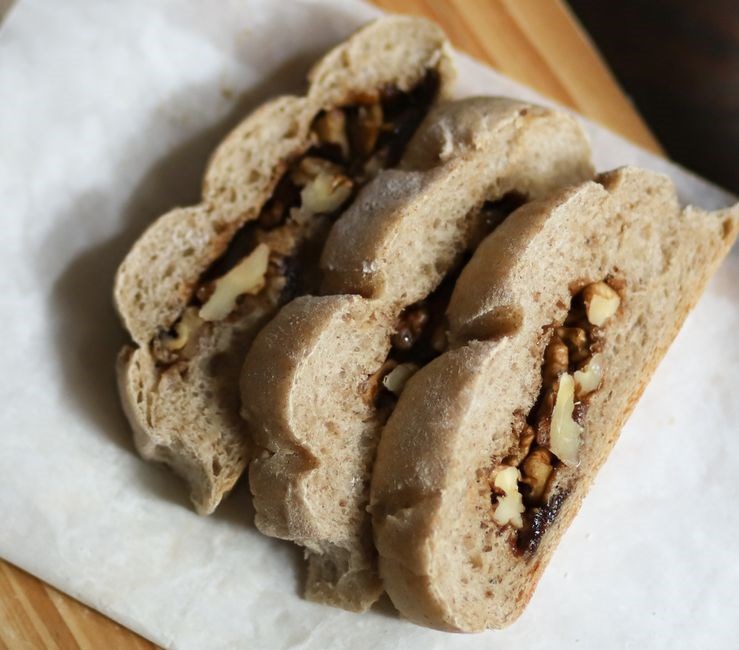
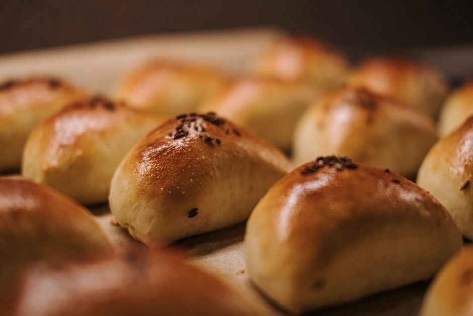
Specialty additives enhance flavor and texture. The PDF details malt powder for caramelization, caraway seeds for rye breads, and dried fruit or nuts for sweet loaves. It explains how to incorporate these ingredients at the right stage—either during the initial mixing or in the final knead to preserve flavor profile. The guide also offers a gluten‑free section, recommending blends of rice, potato, and tapioca flours combined with xanthan gum to mimic traditional elasticity.
Advanced Dough Preparation Techniques
The Elite Gourmet Bread Maker Recipe PDF delves into advanced dough preparation, showcasing autolyse, stretch‑and‑fold, and precise proofing techniques. It outlines optimal hydration, temperature, and timing to develop gluten structure, yielding airy, flavorful loaves with crisp crusts. for home bakers.!
Autolyse, Stretch & Fold, and Proofing
In the Elite Gourmet Bread Maker Recipe PDF, the autolyse step is highlighted as a foundational technique for enhancing gluten development. By mixing flour and water alone and letting the dough rest for 20‑60 minutes, enzymes break down starches, improving extensibility and flavor. The guide recommends a 75‑80% hydration level for most sourdoughs, noting that higher hydration yields a more open crumb.
Stretch and fold is presented as a low‑stress method to build strength without over‑kneading. The PDF details a schedule: after the first 30 minutes of bulk fermentation, perform a series of four folds, each 90 degrees apart, every 30 minutes until the dough reaches the “windowpane” stage. This technique is especially useful in bread‑maker environments where manual kneading is limited.
Proofing instructions emphasize temperature control. The recipe book advises a 75°F (24°C) proofing chamber for the final rise, with a 2‑hour window for 1‑kg loaves. It also provides a “proof‑timer” feature for machines lacking built‑in timers, suggesting a smartphone app or a simple 30‑minute countdown to avoid overproofing. The PDF stresses the importance of a “cold proof” for flavor development, recommending 12‑18 hours at 45°F (7°C) for artisan loaves.
By integrating autolyse, stretch & fold, and precise proofing, the Elite Gourmet Bread Maker Recipe PDF guides users toward consistent, bakery‑quality results while keeping the process accessible for home bakers. for bakers daily!!
Signature Recipe Collections Within the PDF
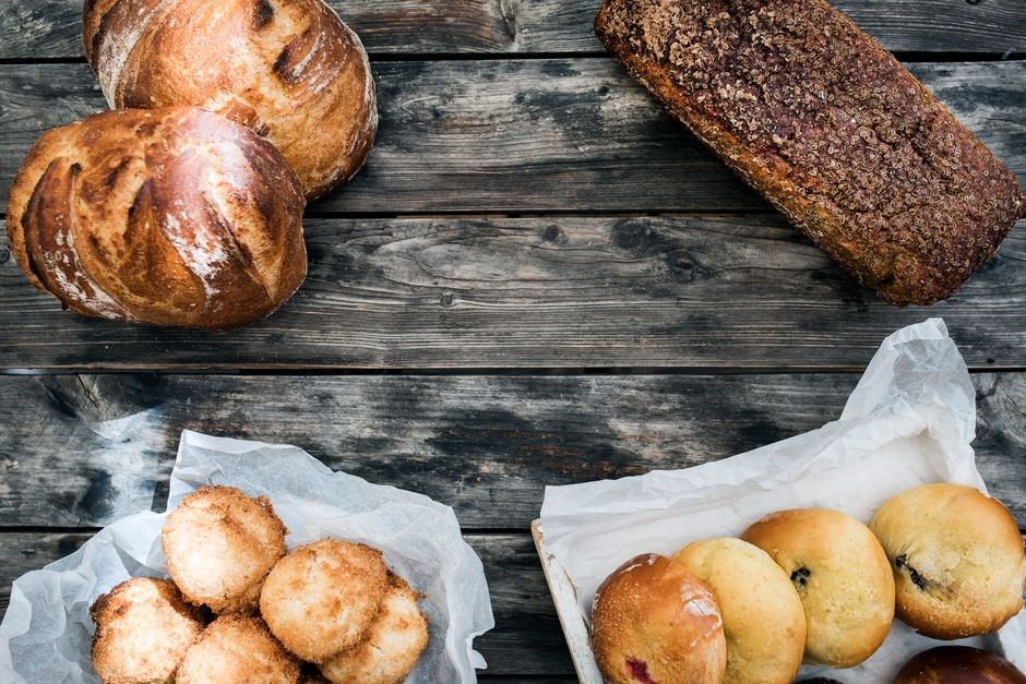
The Elite Gourmet PDF showcases three curated sets: artisan sourdoughs, classic French baguettes, and decadent sweet breads. Each collection includes detailed ingredient lists, machine settings, and step‑by‑step photos for flawless results. Enjoy now.
Artisan Sourdoughs, French Breads, and Sweet Variants
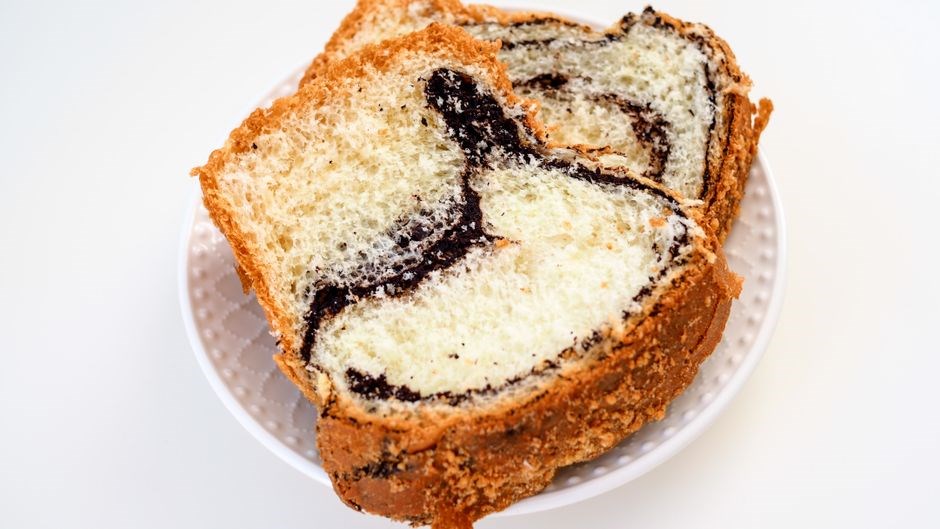
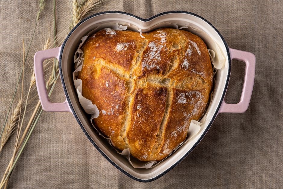
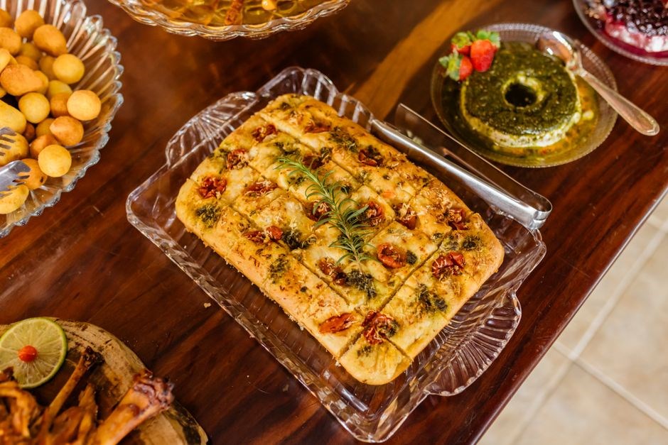
Within the Elite Gourmet Bread Maker Recipe Book PDF, the Artisan Sourdoughs section presents a curated lineup of 12 sourdough varieties, each crafted to showcase distinct flavor profiles—from the tangy, rustic French country loaf to the airy, high‑hydration New‑York style. The recipes emphasize a meticulous autolyse process, precise starter hydration, and a series of stretch‑and‑fold techniques that yield a chewy crumb and a crisp, caramelized crust. Each entry includes a recommended machine setting, optimal proofing temperature, and a step‑by‑step photo guide, ensuring that even novice bakers can replicate the bakery‑quality results at home. The French Breads collection features 10 classic loaves, such as the buttery brioche, the airy pain de campagne, and the iconic baguette. These recipes highlight the importance of dough development, proper kneading, and a final bake at 475°F to achieve a golden‑brown exterior and a tender interior. The Sweet Variants section offers 8 indulgent treats, ranging from cinnamon‑swirl loaf to chocolate‑chip banana bread. Each recipe includes ingredient substitutions for dietary restrictions, tips for achieving the perfect rise, and suggested machine cycles for a flawless finish. Together, these three collections provide a comprehensive, step‑by‑step guide that transforms any bread‑maker into a professional artisan, delivering consistent, restaurant‑style loaves with minimal effort Readers can download printable worksheets to track progress and personalize their baking journey today now
Troubleshooting Common Bread-Making Issues
Common issues such as overproofing, underproofing, and crust problems are addressed with clear diagnostics and corrective actions. Adjust proof time, tweak temperature, and use a baking stone or steam burst for crisp crusts. The PDF offers step‑by‑step fixes for each scenario. See PDF for timing. now.
Overproofing, Underproofing, and Crust Problems
Overproofing manifests as a dough that has expanded excessively, resulting in a weak gluten network and a flat, airy loaf. Signs include “sag” after shaping and a dough that collapses when pressed. To correct, pause the cycle, gently deflate, reshape, and resume a shorter proof. Underproofing produces dense, heavy bread with a tight crumb. Indicators are a dough that has barely risen, a tight surface, and a heavy feel. Solutions involve extending proof time, raising ambient temperature, or adding a small amount of warm water to stimulate yeast activity. Crust issues often stem from steam management and temperature settings. A pale, dull crust may indicate insufficient steam or a lower bake temperature, while an overly hard crust can result from excessive steam or a high oven temperature. Adjusting the steam burst duration, using a water pan, or lowering the bake temperature by 10–15 °C can yield a crisp, golden crust. Consistently monitoring the internal temperature with a probe ensures the loaf reaches 190–200 °F before removal, guaranteeing optimal crumb structure and crust quality; The PDF provides detailed charts for each model, allowing precise adjustments for every scenario.
The guide also offers a troubleshooting matrix, mapping common errors to precise fixes, and a glossary of technical terms for clarity. Users can reference the PDF’s quick‑start sheet to adjust settings on the fly, ensuring each loaf meets professional standards and a detailed FAQ section now!
Legal and Copyright Considerations for PDF Distribution
Distributing the Elite Gourmet Bread Maker Recipe Book PDF demands copyright compliance. Unauthorized copies violate U.S. law, risking civil penalties. Licensed PDFs with DRM should be shared. Obtain permission for bulk use, provide attribution, and verify the license before distribution. and all laws
Licensing, DRM, and Sharing Policies
When distributing the Elite Gourmet Bread Maker Recipe Book PDF, authors and publishers must secure proper licensing agreements that cover both the text and embedded images. Digital Rights Management (DRM) tools—such as Adobe DRM, Microsoft Azure Rights Management, or custom encryption—are commonly employed to prevent unauthorized copying and distribution. The PDF’s license terms should specify whether the file can be shared, printed, or modified. For commercial resale, a separate distribution license is required, often involving a royalty fee per copy or a flat licensing fee. Non‑commercial sharing on personal blogs or forums is usually allowed under a Creative Commons Attribution‑NonCommercial (CC‑BY‑NC) license, provided the original author is credited. However, any redistribution that enables resale or public access without explicit permission violates copyright law and can result in civil or criminal penalties. Users should always verify the license status before sharing, and any shared copies should include a clear copyright notice and a link to the original source. When using DRM‑protected PDFs, ensure that the recipient’s device is compatible with the chosen DRM system; otherwise, the file may become inaccessible. In summary, respecting licensing terms, applying appropriate DRM, and adhering to sharing policies protects both the creator’s rights and the user’s legal compliance. Compliance with these policies ensures that the PDF remains a resource for bakers worldwide while safeguarding the creator’s property!